STANDARD CYLINDER With identical fitting length as existing cylinders without piston
0-stroke compatible
ZK
ZKS
SHORT CYLINDER With extremely shortened fitting length
0-stroke up to %42 shorter
ZF
ZFF
ZFK
ZFU
ZFB
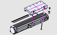
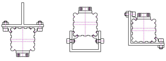
GUIDING CYLENDER With external an adjustable slide guide
For high Loads
ZP
PARALLEL CYLINDER for high loads and moments in every direction
double action force
central port
ZGS
ZGK
ZGF
ZGFK
GRIPPING CYLINDER Gripping and clamping functions
Opening & closing functions
ZTS
ZTK
ZTF
TANDEM CYLINDER For high moments in longitudinal direction
ZDS
ZDK
ZDF
ZDFK
DOUBLE ACTION CYLINDER Double action force
pressing, embossing, punching etc.
FB
MB
PB
KT
ACCESSORIES Mounting brackets
Middle support
Swinging bridge
Cross support etc.
SAFETY REGULATIONS
The LANAMATIC cylinder is safe and made according to the latest technical research.
There could be a danger if
The cylinder will be used, mounted and maintained either improperly or by unqualified staff
The cylinder will not be used according to the regulations
The accident prevention regulations (UVV, VDE), the safety and installation regulations will not be respected
Working methods,restricting the function adn operation safety of the cylinder, have to be omitted.
The cylinder is exclusivelyto be used in the scope of its technical data; any other use beyond this is out of the regulations.
The manufacturer is not liable for damages caused by such an improper use.
In case of mounting, rebuilding or maintaning the energy supply has to be removed.
In case of maintenance, extension or rebuilding it is advisable to remove the cylinder from the working area and to do the work out of the danger zone.
When mounting, connecting, adjusting, bringing into service and testing the units it should be guarenteed that no mechanic or another person could operate the cylinders by mistake.
Additional bores, thread of attachments, being not offered as accessories, can only be applied after consulting the LANAMATIC AG.
Should a cylinder be operated in the neighbourhood of abrasive dust or aggressive vapour, the prior approval of LANAMATIC AG is necessary.
.Otherwise, the safety and accident preventation regulations of the operation place are valid.
NOTES
These data are to be used as product information and not as granted properties by law.
Any claim for damages againts us is to be ruled out, without considering the cause in law, unless intention or gross negligence could be applied to us.
All rights reserved for technical changes, omissions and fallacy
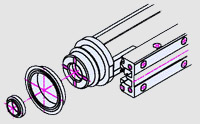
MOUNTING INSTRUCTION
:Lubricate piston seals and cushioning ring lightly
Mount piston seals on piston
Put cushioning ring into the slot.
Take care that the smaller Ø of the ring is outside.
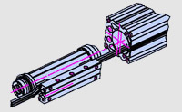
:Lubricate sealing strip lightly.
Bend up one end and insert it into yoke.
Insert long end of sealing strip into the tube profile and put the yoke into the tube profile
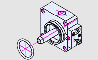
:Endcap is preassembled with strip cover and cushioning pin.
Lubricate o-ring and mount it.
:Push yoke to the end and insert end cap.
On one side port insert flat sealing and tighten the special screws.
:Insert cover strip and clamp it with grub screw.
Pull through yoke.
Measure exact length and clamp it on other side.
:Pull the sealing strip tight (approx. 0.5 - 1 % of the length), stretch it and fix with grub screw with pin
Cut off overstanding sealing strip Insert wiper, screw on head wiper and tighten cover strip with it.
:Fit grub screw with adhesive (Loctite)
Slide on guide carriage and adjust guiding bar with grub screws lightly
Beat guide carriage lightly with a rubber hammer from the side.
Check clearance, readjust if necessary
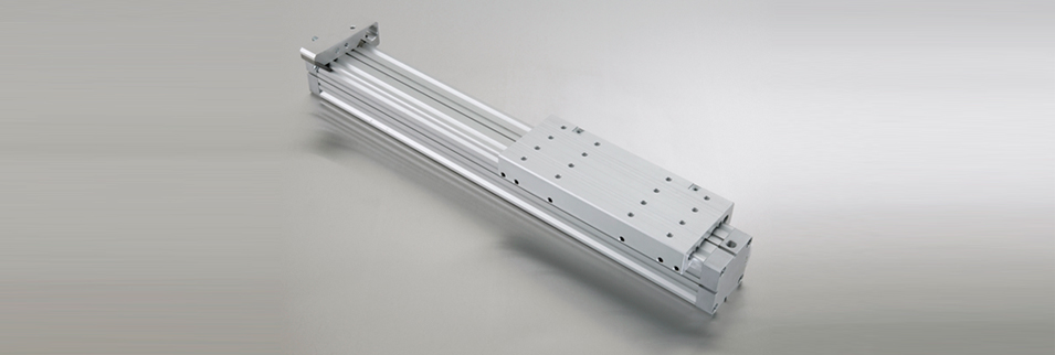
Technical Information
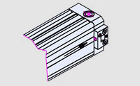
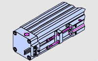
Construction
Rodless cylinder with direct power transmission through the tube slot onto the yoke
Stroke
Variable up to 6000mm, higher on request
Fitting Position
Variable
Operation
Double acting with adjustable end-of-travel cushioning
Operating Pressure
2 ... 8bar
Operating Temparature
-20° C ... +80° C
Medium
Filtered and slightly oiled or not lubricated compressed air
Material
Aluminum parts made of highstrength alloy sealing parts made of oil resistant plastics and elastomers
Weight
Cylinder
Force/6 bar
Cushioning
ZS
ZF
ZFF
Weight/Stroke
18
140 N
15 mm
0.3 kg
0.4 kg
0.6 kg
1.5 kg/1000 m
25
270 N
18 mm
0.6 kg
0.9 kg
1.1 kg
2.6 kg/1000 m
32
440 N
24 mm
1.1 kg
1.5 kg
2.2 kg
3.6 kg/1000 m
40
680 N
34 mm
1.8 kg
2.8 kg
3.8 kg
4.8 kg/1000 m
50
1060 N
40 mm
3.2 kg
4.9 kg
6.4 kg
7.4 kg/1000 m
63
1680 N
49 mm
5.6 kg
8.0 kg
10.4 kg
10.0 kg/1000 m
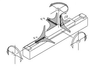
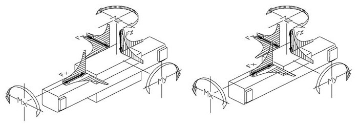
LOADS
All data concerning forces and torques refer to a speed of v<0.35m/s.
Observation keeping the indicated values ensures maximum service life, minimum noise and optimum operating results.
Higher speeds reduce the admissible forces
ZS Standard Cylinder
Cylinder
V max <= 0.35 m/s
V or port F
Torques
Fx(N)
Fy(N)
Fz(N)
F kab.
0.75 m/s
F kab.
1 m/s
F kab.
1.5 m/s
Mx(Nm)
Fy/ Fz
My(Nm)
Fx/Fz
Mz(Nm)
Fx/Fy
18
140
80
300
80
40
20
1
3
3
25
270
110
480
155
90
40
2
13
13
32
440
165
650
280
155
70
3.5
25
25
40
680
225
800
500
290
125
5.5
40
40
50
1060
325
1060
790
420
195
10
65
65
63
1680
435
1680
1500
850
370
16
100
100
ZF Guiding Cylinder
Cylinder
V max <= 0.35 m/s
V or port F
Torques
Fx(N)
Fy(N)
Fz(N)
F kab.
0.75 m/s
F kab.
1 m/s
F kab.
1.5 m/s
Mx(Nm)
Fy/ Fz
My(Nm)
Fx/Fz
Mz(Nm)
Fx/Fy
18
140
370
370
100
58
26
3.5
6
6
25
270
800
800
280
160
65
10
20
20
32
440
1200
1200
510
300
140
25
45
45
40
680
1600
1600
1000
550
250
40
75
75
50
1060
2100
2100
1500
850
380
80
150
150
63
1680
2800
2800
2500
1400
610
110
250
250
ZFF Double Guiding Cylinder
Cylinder
V max <= 0.35 m/s
V or port F
Torques
Fx(N)
Fy(N)
Fz(N)
F kab.
0.75 m/s
F kab.
1 m/s
F kab.
1.5 m/s
Mx(Nm)
Fy/ Fz
My(Nm)
Fx/Fz
Mz(Nm)
Fx/Fy
18
140
550
550
150
80
31
5.2
9
9
25
270
1200
1200
420
210
80
15
30
30
32
440
1800
1800
750
400
170
37
67
67
40
680
2400
2400
1500
750
300
60
110
110
50
1060
3200
3200
2200
1150
460
120
220
220
63
1680
4200
4200
3700
1900
740
170
370
370
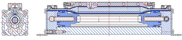
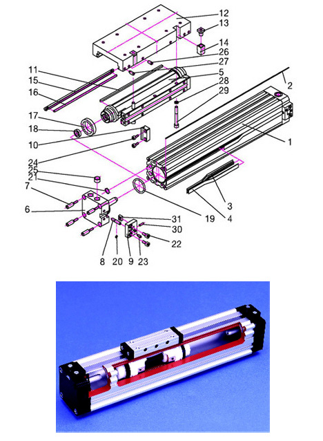
Pos
DESCRIPTION
MATERIAL
1
Tube
Al Mg Si 0.5 Anodized
2
Rond Profile
TPU
3
Sealing Strip
PA
4
Cover Strip
Stainless Steel
5
Yoke
Al Anodized / POM
6
Endcap
Al Anodized
7
Special Screw
Zinc-Plated Steel
8
Cushioning Pin
Stainleess Steel
9
Strip Cover
POM
10
Head Wiper
POM
11
Wiper
POM
12
Carriage
Al Anodized
13
Cone Nut
Zinc-Plated Steel
14
Clamp Wedge
Al Anodized
15
Guiding Bar
POM
16
Press Bar
Stainleess Steel
17
Piston Seal
PU
18
Cushion Ring
NBR
19
O-ring
NBR
20
O-ring
NBR
21
Flat Seat
NBR
22
Countersunk Screw
Zinc-Plated Steel
23
Grup Screw With Pin
Zinc-Plated Steel
24
Cylinder Head Screw
Zinc-Plated Steel
25
Plug Screw
Zinc-Plated Steel
26
Grup Screw
Steel
27
Grup Screw With Pin
Steel
28
Plain Washer
Zinc-Plated Steel
29
Cylinder Head Screw
Zinc-Plated Steel
30
Grup Screw
Steel
31
Square Nut
Zinc-Plated Steel
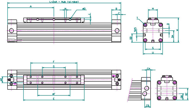
ZS Standard Cylinder
Ø
A
AF
AM
B
C
CA
CB
D
DA
DB
DC
DD
E
F
G
J
M
N
ØO
S
T
U
W
Ø 18
80
50
10
16.5
6.5
-
-
M7x1/6
15.5
-
-
-
103
75
-
3
15.5
M3x6
Ø 3.5
23.5
M3x7
30
39
Ø 25
100
70
13
20
8.5
7
13
G1/8x8
25.5
14
28
18.5
131
100
50
3.5
20
M4x7
Ø 4.5
33
M4x9
42
53
Ø 32
120
100
16
20
8.5
7
13
G1/8x8
32
16
34.5
21
171
140
70
4.5
25
M5x9
Ø 5.5
41
M5x10
52
65
Ø 40
150
140
22
23
13
11
14.5
G1/4x12
37.5
18.5
41
29.5
220
180
90
5
33
M6x10
Ø 7
51
M6x12
63
79
Ø 50
180
180
29
23
13
12
14
G1/4x12
47.5
22.5
47.5
37
280
220
110
6.5
42
M8x12.5
Ø 7
63
M8x12
78
96
Ø 63
215
230
40
29
13
12.5
15.5
G3/8x12
59.5
24.5
59.5
44.5
333
280
140
8
54
M8x15
Ø9
78
M8x12
93
113.5
Example for order :
ZS Ø 25 Standart cylinder with stroke 100mm
Order number.
1
2
5
0
-
0
0
0
0
-
0
1
0
0
Port Standart
1
2
5
0
-
0
0
0
1
-
0
1
0
0
Port Underneath
1
2
5
0
-
0
0
0
2
-
0
1
0
0
One Side Port
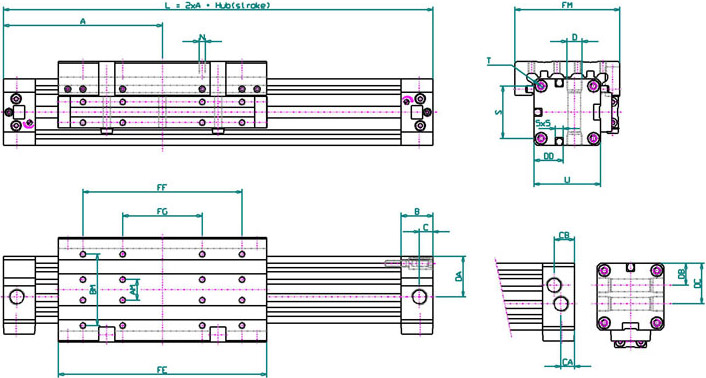
ZF Guiding Cylinder
Ø
A
AM
B
BM
C
CA
CB
D
DA
DB
DC
DD
FE
FF
FG
FM
FW
N
S
T
U
Ø 18
80
10
16.5
35
6.5
-
-
M7x1/6
17.5
-
-
-
103
75
-
50
39
M4x7.5
23.5
M3x7
30
Ø 25
100
13
20
45
8.5
7
13
G1/8x8
25.5
14
28
18.5
131
100
50
66
53
M4x8
33
M4x9
42
Ø 32
120
16
20
55
8.5
7
13
G1/8x8
32
17.5
34.5
21
171
140
70
80
65
M5x10
41
M5x10
52
Ø 40
150
22
24
70
13
9.5
14.5
G1/4x12
37.5
20
42
29.5
220
180
90
97
79
M6x12
51
M6x12
63
Ø 50
180
29
24
85
13
9.5
14.5
G1/4x12
47.5
26
52
37
280
220
110
116
96
M8x16
63
M8x12
78
Ø 63
215
40
30
105
13
11
18.5
G3/8x12
59.5
30
62
44.5
333
280
140
136
113.5
M8x16
78
M8x12
93
Example for order :
ZF Ø 25 Guiding cylinder with stroke 100mm
Order number.
3
2
5
0
-
0
0
0
0
-
0
1
0
0
Port Standart
3
2
5
0
-
0
0
0
1
-
0
1
0
0
Port Underneath
3
2
5
0
-
0
0
0
2
-
0
1
0
0
One Side Port
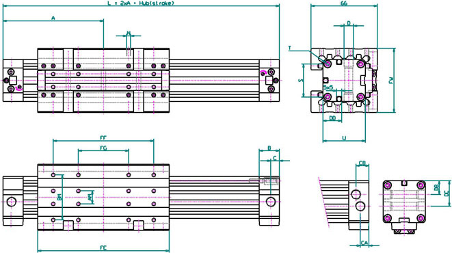
ZFF Double Guiding Cylinder
Ø
A
AM
B
BM
C
CA
CB
D
DA
DB
DC
DD
FE
FF
FG
FM
FW
N
S
T
U
Ø 18
80
10
16.5
35
6.5
-
-
M7x1/6
17.5
-
-
-
103
75
-
50
48
M4x7.5
23.5
M3x7
30
Ø 25
100
13
20
45
8.5
7
13
G1/8x8
25.5
14
28
18.5
131
100
50
66
64
M4x8
33
M4x9
42
Ø 32
120
16
20
55
8.5
7
13
G1/8x8
32
17.5
34.5
21
171
140
70
80
78
M5x10
41
M5x10
52
Ø 40
150
22
24
70
13
9.5
14.5
G1/4x12
37.5
20
42
29.5
220
180
90
97
95
M6x12
51
M6x12
63
Ø 50
180
29
24
85
13
9.5
14.5
G1/4x12
47.5
26
52
37
280
220
110
116
114
M8x16
63
M8x12
78
Ø 63
215
40
30
105
13
11
18.5
G3/8x12
59.5
30
62
44.5
333
280
140
136
134
M8x16
78
M8x12
93
Example for order :
ZFF Ø 25 Guiding cylinder with stroke 100mm
Order Number
3
2
5
1
-
0
0
0
0
-
0
1
0
0
Port Standart
3
2
5
1
-
0
0
0
1
-
0
1
0
0
Port Underneath
3
2
5
1
-
0
0
0
2
-
0
1
0
0
One Side Port
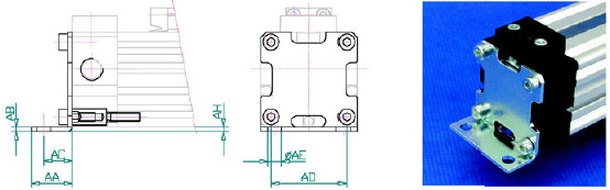
FB Mounting brackets
Cylinder
Ø mm
AA
AB
AC
AD
AE
AH
Order Number
Ø 18
15
2
10
20
Ø 6
2
1182-0001
Ø 25
18
2
12.5
30
Ø 6
2
1252-0001
Ø 32
20
2.5
13.5
40
Ø 7
3
1322-0001
Ø 40
30
3
17.5
50
Ø 9
3.5
1402-0001
Ø 50
28
3
20
60
Ø 9
3
1502-0001
Ø 63
30
3
21
75
Ø 11
4.5
1632-0001
The order No. given includes 2 mounting brackets and 8 screws.
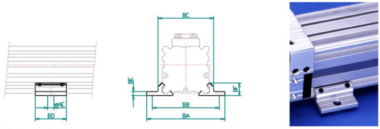
MB Middle Support
Cylinder Ø mm
AE
AH
BA
BB
BC
BD
BE
BF
Order Number
Ø 18
Ø 6
2
56
46
36.5
23
2.5
8.25
1183-0001
Ø 25
Ø 6
2
70
60
50
28
3.5
11
1253-0001
Ø 32
Ø 7
3
85
73
61.5
33
4
13.8
1323-0001
Ø 40
Ø 9
3
105
90
75
38
4.5
16
1403-0001
Ø 50
Ø 9
3
122
106
91
43
5
19
1503-0001
Ø 63
Ø 11
4.5
144
125
107
48
6
22
1633-0001
The order No. given includes 2 mounting brackets and 4 screws.
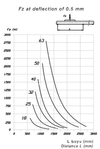
Deflection Diagram
MB middle support
When using very long cylinders or applying heavy loads, the tube deflection is to be taken into consideration. One or more middle supports are to be used according to the admissible deflection.
Example: A cylinder Ø 25 should deflect by a maximum of 0.5 mm when applying a force FZ of 500N. According to the diagram the cylinder can be 750 mm long. Longer cylinders must have a middle support.
Other possibilities In case very long cylinders are installed without supports, an additional profile can be used as a support.
Examples: All versions with middle support and standart profiles.
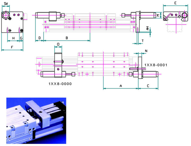
AS Stop Adjustment
Cylinder Ø mm
A
ZF/ZFK
AH
B
ZF/ZFK
C
D
E
F
G
H
M
N
O
SW
T
Ø 18
80/57.5
2
113/90.5
32
Max. 25
57
43.5
8
23.5
M10x1
8
15
13
M3x10
Ø 25
100/67.5
2
117.5/85
37
Max. 40
72
57
12.5
33
M14x1.5
10
20
17
M4x10
Ø 32
120/77.5
3
135.5/90
70
Max. 30
84
70
14.5
41
M14x1.5
12
20
17
M5x12
Ø 40
150/95
3
165/110
65
Max. 50
105
93
16
51
M25x1.5
15
30
32
M6x15
Ø 50
180/105
3
195/140
80
Max. 65
126
102
22.5
63
M25x1.5
15
30
32
M8x20
Ø 63
215/125
4.5
250/160
80
65
140
118.5
20
78
M25x1.5
15
40
32
M8x20
Example for Order : AS25 stop adjustment shiftable gor ZF25 or ZFK25 (without shock absorbers)
Order Number.
1
2
5
8
-
0
0
0
0
Cylinders
3D IGES
Click on the buttons to download the file format drawings. >