 |
| KSF : |
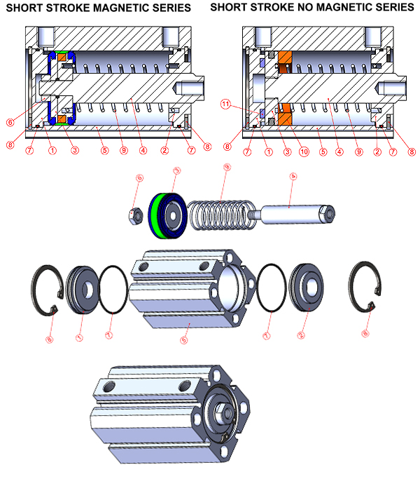
SHORT STROKE CYLINDERS WITH SINGLE ACTING (SPRINGED FROM FRONT) |
| |
|
|
 |
| KSF-A: |
SHORT STROKE MAGNETIC CYLINDERS WITH SINGLE ACTING (SPRINGED FROM FRONT) |
| |
|
|
 |
| Working Fluid : |
Filtered and lubricated or filtered and not lubricated air. |
| |
| Operating Temperature Range : |
Polyurethane (PU) : -20° C......+80° C
Viton (FKM) : -30° C......+150° C |
| |
| Max. Work Pressure : |
10 Bar
|
|
 |
|
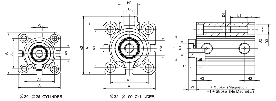
| Cylinder Ø mm |
Rod Ø mm |
Thrust and traction forces (6 bar) |
| (mm) |
(mm) |
Thrust Force (N) |
Traction Force (N) |
| 20 |
10 |
145 |
9 |
| 25 |
12 |
270 |
13 |
| 32 |
16 |
397 |
16 |
| 40 |
16 |
654 |
23 |
| 50 |
20 |
1052 |
30 |
| 63 |
20 |
1732 |
35 |
| 80 |
25 |
2792 |
60 |
| 100 |
30 |
4386 |
100 |
|
|
| VARIANTS FROM STANDARD SYSTEM |
| R1 |
: |
Stainless Steel Piston Rod ( SS 304-SS 316 ) |
| R4 |
: |
Stainless Steel Nut for Piston Rod ( SS 304 ) |
| R5 |
: |
Piston Rod as CK45 ( Hard Chrome Plated ) |
| M1 |
: |
Extended male Piston Rod Thread |
| M3 |
: |
Special Piston Rod Thread |
| M4 |
: |
Extended Piston Rod |
| K1 |
: |
Seals for Max. 150 C ( Viton ) |
| K4 |
: |
Piston Rod Seal Viton |
|
|
|